

VoidX-DSPModule is a tiny hardware platform specifically designed for audio DSP applications, it is a low-cost solution that enables manufacturers to integrate a complete DSP system into their products without effort. VoidX-DSPModule features two high-resolution inputs (110dB SNR) and outputs (112dB SNR) and provides lots of I/O interfaces:
- Bluetooth and Wi-Fi connectivity to VoidX-Control on mobile devices;
- USB, Bluetooth and Wi-Fi connectivity to VoidX-Control on PC/MAC devices;
- MIDI IN/OUT: VoidX-DSPModule suports direct connection to standard MIDI connectors, no external circuitery required;
- 5V-14V wide supply range, you can also power VoidX-DSPModule via the on-board USB connector;
- Extensive set of GPIOs (digital, analog, PWM, I2C, SPI, ..);
- I/O Expander interface with shift registers to support hundreds of I/O connections (e. g. LEDs and push-buttons);
- Graphic display I2C and SPI support;
- VoidX-DSPModule provides external 3.3V – 500mA supply for auxiliary circuitry;
- USB/JTAG programming and debugging capability.
- 240MHz dual-core CPU module with 2MB RAM and 8MB Flash: ESP32-S3-WROOM-1(N8R2).
PCB Pinout
VoidX-DSPModule features a 2×20 2.54mm header for powering, GPIOs and other interfaces and a 2×5 2.54mm header for high resolution audio interfacing. Below is some recommendation for correct usage.


White pins are directly connected to MCU’s GPIOs. Their number refers to the exact MCU enumeration, for example GPIO10 connected on main connector’s pin11 is internally connected to pin IO10 of ESP32-S3. Pins 26 and 27 are shared with the I/O expander interface (clock & CS), they can be used as regular GPIOs only if I/O expander interface is not used.
Yellow pins 1 and 2 are directly connected to the on-board USB connector, they can be used to place an equivalent USB connector elsewhere. USB connection can be used for serial/USB interface for PC/MAC communication and for USB programming via ESP-IDF or Arduino IDE, no push-buttons or external boards are required for USB programming.
Yellow pins 9 and 12 are internally connected to IO19 and IO20 of ESP32-S3, they can be used for JTAG debugging or as normal GPIOs if JTAG programming/debugging is not used.
Red pins are used for power rails. The board must be supplied ONLY by using pins 39 (GND) and 40 (5-12V). Pin 14 is only used as output (3.3V – 500mA), NEVER provide 3.3V to this pin. Pin 5 of the audio connector is internally connected to pin 40 of main connector, we strongly suggest to use only pin 40 for powering, pin 5 of the audio connector can be used as facility to provide power rails (along with pin 6 OUT GND) in multi-board systems, in most applications it is leaved unconnected.
Grey pins can be used as regular GPIOs or not, depending on the application.
- Pins 3, 4, 5, 6 are used for direct connection to MIDI connectors (see “Architecture overview” section), no external circuitry required. These pins can never be used as regular GPIOs;
- Pins 7 and 8 are used for MIDI UART Tx/Rx. Logic levels on these pins are strongly correlated with signals on pins 3, 4, 5, 6. If MIDI is used, you can not use this pins for other purposes, if MIDI is not used you can use these pins as regular GPIOs but be careful if using them as inputs: pin 8 is internally conected to a 470Ω pull-up resistor and pin 7 internally drives the base of a NPN bjt via a 220Ω resistor (see “Architecture overview” section).
- Pins 19 and 20 are shared with the internal I2C channel used to communicate with the ADC chip, pull-ups are internally connected (3.3kΩ). You can safely use these pins to communicate with other I2C slaves. Use this pins for other purposes only if you really know what you are doing.
- Pins 21, 22, 23, 24, 25, 28, 29, 30, 31, 32, 33, 34, 35, 36 are part of the shift-register I/O Expander circuitry (see “Architecture overview” section). DIGITAL IN 0-3 pins are inputs to the 4 LSBs of an 8-bit input shift register; DIGITAL OUT 0-7 pins are outputs of a 8-bit output shift register; pins 25 and 28, along with pins 26 ad 27, can be used to daisy-chain other shift registers for unlimited I/O capabilities.
Orange pins are for analog pseudo-differential outputs. Pins 7 and 8 of the audio connector are connected to the internal DAC (PCM5102) outputs, respectively R and L. The DAC provides 2.1V RMS ground centered outputs with 112 dB SNR. Pin 6 OUT GND is the converters’ operating ground and can be used as analog ground reference. In very demanding audio applications microvolt ground-differences between different points of the system can be a problem (inducted hiss noise, supply noise), in these cases, using OUT GND pin as pseudo-differential reference terminal solves the problem, allowing to maintain the full SNR on the whole signal path. A differential amplifier that produces the analog difference between OUT signal (L or R) and OUT GND should be placed as close as possible to the output connector.
Light Blue pins are for analog differential input. Pins 3 ,4, 5, 6 of the audio connector are directly connected to the internal ADC (PCM1865) inputs: pins 3 and 4 correspond to the L differential pair, pins 1 and 2 correspond to the R differential pair. The internal ADC provides 110dB, 4.2V RMS differential inputs (2.1V RMS is the range on each input pin). Input signals must be connected to the module through DC-blocking capacitor, input impedance on each input pin is 10kΩ.
Architecture overview

DC/DC Converter: an internal converter provides robust 3.3V from a 5-12V input voltage, it is also possible to use this 3.3V (max 500mA) for external circuitry. VoidX-DSPModule can be powered via the main connector pins 39 and 40 or via the USB connector simultaneously, no risk of power supply conflict.
CPU Module: ESP32-S3-WROOM-1(N8R2) is at the heart of the system. It is a 240MHz dual-core system with 2MB RAM and 8MB Flash. We developed an extremely efficient DSP library that performs much better than Espressif’s DSP benchmark for most common DSP operations. With VoidX-DSPModule you can access all ESP32 main features: Bluetooth, Wi-Fi, Low power operation, and many more.
Power-ON LED: a red LED is connected to ESP-IO41 through a 220Ω resistor, such LED is usually used as a power-ON indicator. It is possible to PWM-drive the LED to decrease it brightness.
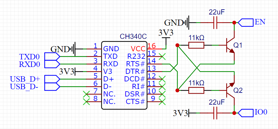
USB-Serial interface: The USB-Serial interface is based on CH340C chip and can be used for serial communication and programming via ESP-IDF or Arduino IDE. USB_D+ and USB_D- Connections come directly from the USB connector and are also exposed in the main connector for flexibility (pins 1 and 2).
USB-JTAG: It is possible to program and debug VoidX-DSPModule via USB-JTAG using ESP-IDF. JTAG programming makes it much easier to build complex applications. Pins 9 and 12 of the main connector are directly connected to ESP32-S3’s IO19 and IO20, respectively (D- and D+), these pins can be connected to an external USB connector to provide USB capability.

I/O Expander: VoidX-DSPModule integrates an I/O Expander circuitry based on shift registers. ESP32-S3’s IO47, IO21, IO7, IO48 can be driven by an SPI peripheral to maximize speed. SERIAL_IN, SERIAL_OUT, SERIAL_CLOCK (IO21) and SERIAL CS (IO47) are exposed in the main connector, respectively pins 25, 28, 26, 27. SERIAL_OUT can be connected to the serial input of an external output shift register, SERIAL_IN can be connected to the serial output of an external input shift register. By adopting this daisy-chain strategy it is possible to support up to hundreds of I/O connections. DIGITAL_IN0-3 connections are exposed in the main connector (pins 21-24), DIGITAL_OUT0-7 connections are exposed in the main connector (pins 29-39).

MIDI I/O: no more worries about MIDI, VoidX-DSPModule implements a standard 3.3V MIDI circuitry and supports direct connection to standard MIDI connectors (pins 4 and 5). The image descibes all the internal connection, you need to be aware of them when you use ESP32-S3’s IO13 and IO14 for no-MIDI purposes.
ADC/DAC reset: ESP32-S3’s IO39 is reserved for future use as ADC/DAC reset pin, it is currently not used.
I2C: ESP32-S3’s IO15 and IO16 (SCL – SDA) are used for I2C communication with the internal ADC PCM1865 (address 1001 010), these two pins are internally connected to 3.3kΩ pullup resistors. These pins can be safely used for adding I2C slaves, use them with caution for non-I2C purposes.
I2S: ADC and DAC audio flows via standard I2S, the following ESP32-S3 pins are used:
- IO38 – MCLK – currently unused but reserved for future use;
- IO18 – BCK;
- IO17 – LRCK;
- IO2 – MOSI (Data IN of the DAC)
- IO40 – MISO (Data OUT of the ADC).
ADC/DAC analog interface: audio connector differential IN pins are directly connected to the internal ADC, no other circuitry involved. DAC chip outputs (L and R) reach the audio connector OUT pins through a 470Ω resistor, audio connector OUT pins are also grounded with 2.2nF capacitor to suppress high frequencies.
Mechanical data
VoidX-DSPModule size is only 70x39mm, it is designed to be easily integrated in any design, it also features four M3 screw slots for robust mounting when needed. Below a picture of all relevant measures: total size, M3 screw slot diameter and spacing from margins, USB connector coordinates. Contact us for further info or customization.
